Vector Reflection (2D Derivation)#
This notebook will work through the explanation of determining the 2D vector reflection from a surface. I had a problem where I needed to determine the reflected vector from an incident vector in two dimensions. There are a lot of pages out there with good explanations. But a lot of seemingly conflicting information caused me to question my knowldge and write this article. This source is quite nice. It walks you through the steps and develops a valid relationship:
Unfortunately, the formula is derived with both the incident vector and reflected vector pointing away from the surface. The system diagram can be seen in figure 1:
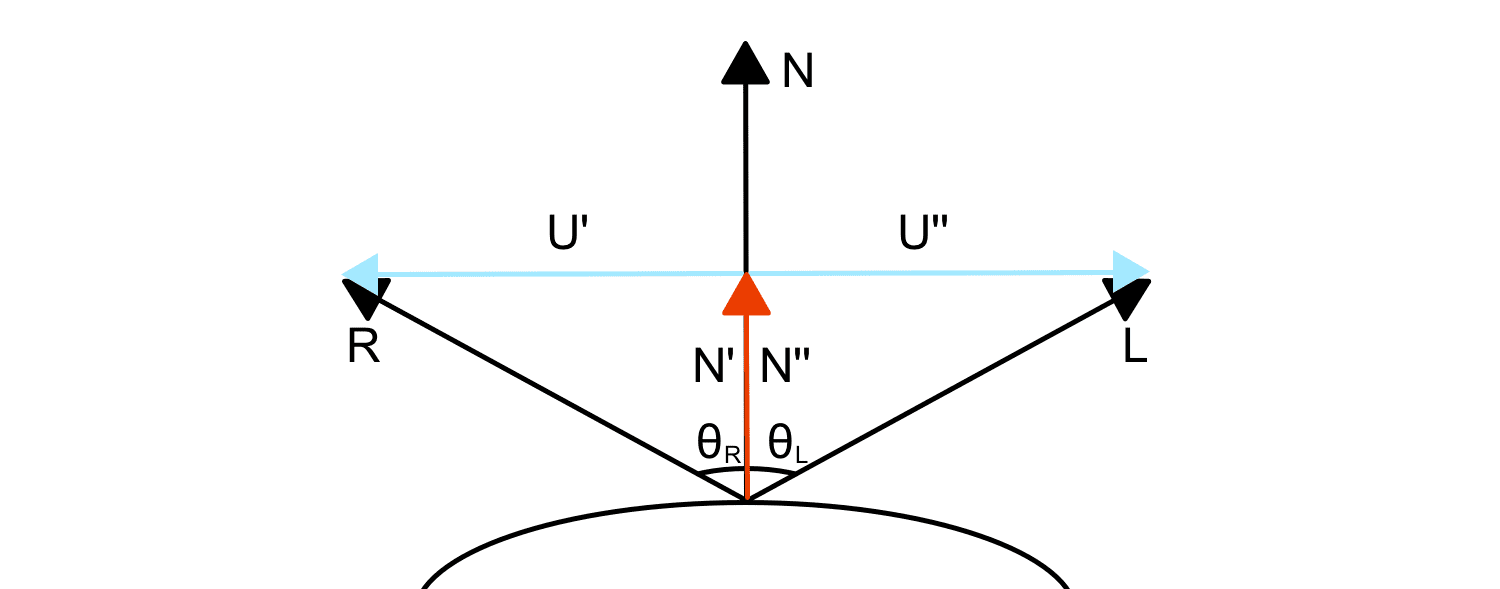
I don’t care for this derivation. I understand why this convention was chosen, it makes derivation easy. To use this equation, you must take the incident vector’s negative. To me, it seems wrong. Why should I have to negate the input before it is used in a calculation? This isn’t the end of the world, but it is something to be aware of.
I wanted something that modelled the system directly with the incident vector pointing at the surface it would hit. See figure 2 for details:
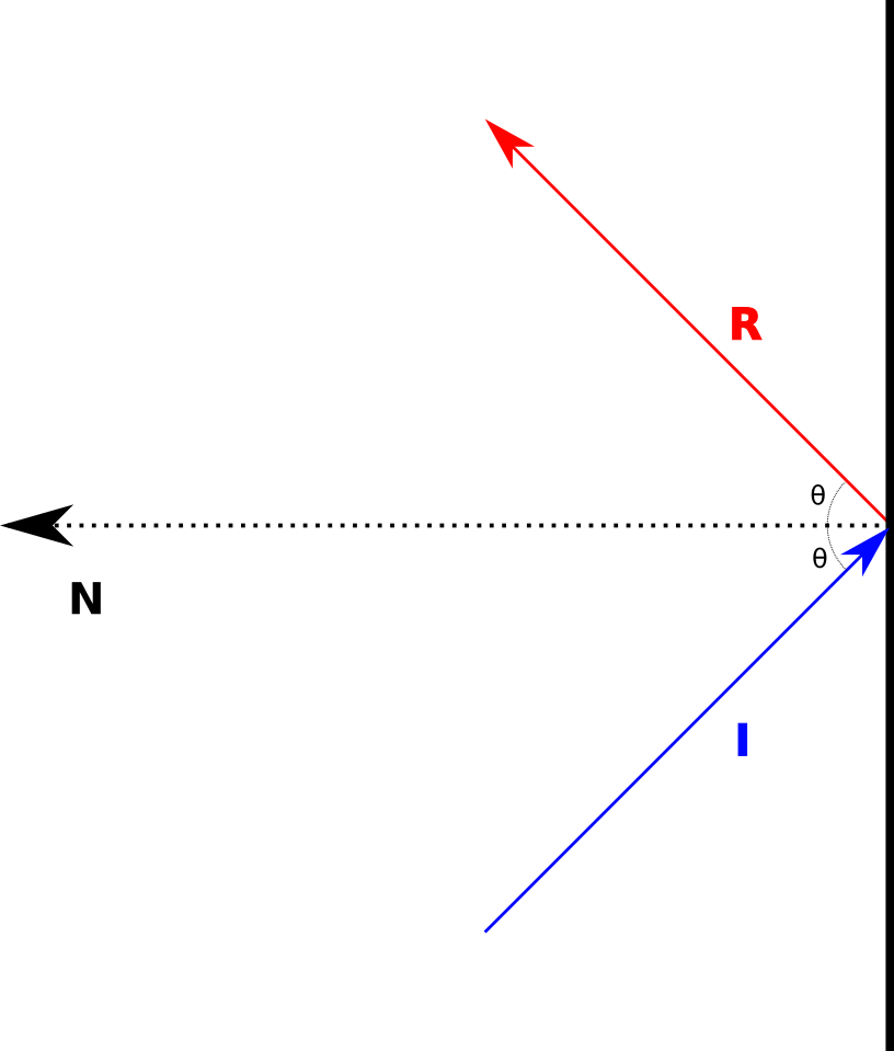
Figure 2 - Incident vector, I, reflecting from a surface with normal N as vector R.#
I wanted something that would not require changing any of the inputs. I wanted something that could use the inputs directly. Here are the components that are illustrated in figure 1:
\(\vec{I}\) - The incident vector.
\(\vec{R}\) - The reflected vector.
\(\theta\) - The angle of incidence is equal to the angle of reflection. This angle is measured from the plane’s normal vector.
\(\vec{N}\) - The normal vector of the plane.
This source on StackExchange lists the formula suited for the system I am interested in. I wanted to understand where this formula comes from and how it is derived. The rest of the article works through that process. If we examine the system above, we can see that it is symmetrical. We know this because the angle of incidence must equal the angle of reflection.
Projection#
If we project \(\vec{I}\) to the normal vector, \(\vec{N}\) we will obtain \(\vec{N'}\) (figure 3).
An essential fact here is that by symmetry, we expect that projecting \(\vec{R}\) to \(\vec{N}\) will produce \(-\vec{N'}\). This took me a while to build an intuition for. It took a careful examination of the problem to grasp it. The projection of \(\vec{I}\) or \(\vec{R}\) maintains their direction, pointing towards the reflection plane or away from the plane. This is the key to the difference in the formula derivations from the previously mentioned sources.
Ride the Point#
If you imagine you are projecting particles at the surface, and they obey Snell’s law and reflect off the surface (ignoring collisions and energy loss, etc.). We want to predict the location of this particle after it is reflected. Boiling it down, we want to predict the reflected direction vector. For this system, if we have a point at the tail of \(\vec{I}\) (figure 3) and we want to move it to the tip of \(\vec{R}\) how do we do that?
Note
See [appendix 1](Vector Addition and Subtraction) for details about the assumption of projecting particles and vector addition and subtraction.
From the diagrams below (figure 3 and figure 4), if we project \(\vec{I}\) onto \(\vec{N}\) we get \(\vec{N'}\)
We can solve for \(\vec{U}\):
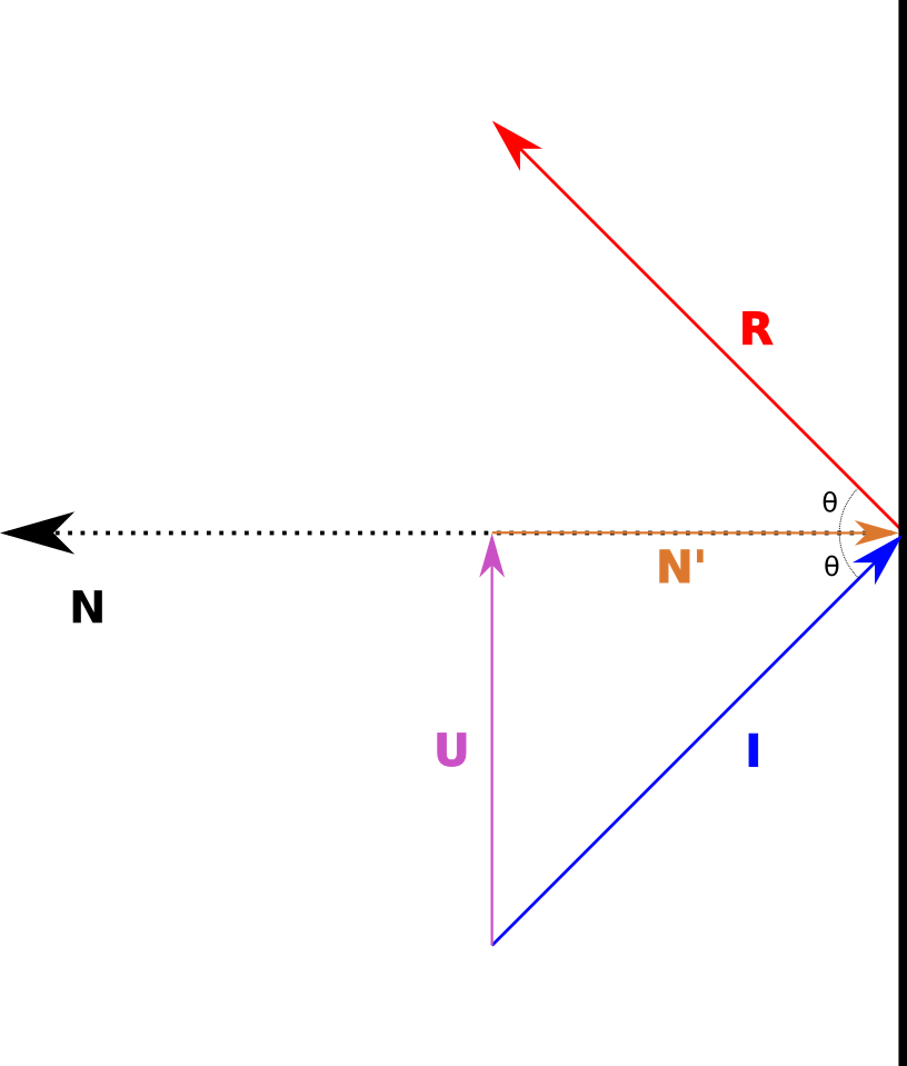
Figure 3 - Vector U defined.#
By symmetry, we assume that the vector from the tail of \(\vec{N'}\) to the tip of \(\vec{R}\) is equal to \(\vec{U}\):
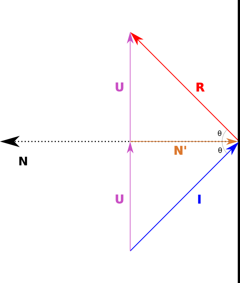
Figure 4 - The complete system, how to get from the incident vector to the reflected vector.#
This means:
Solving for \(\vec{R}\):
Expand and simplify:
Conclusion#
The equation we need is (1). It defines how to construct the reflection vector from the incident vector. The derivation was straightforward (once I had a better grasp of some of the basics). I should have had a better understanding when I learned this years ago. I might have, but in the ensuing years, that knowledge was lost.
Appendix#
Vector Addition and Subtraction#
As an aside, I took a quick refresher on the basics of vector addition and subtraction. It is a seemingly simple topic that every first-year science student is acquainted with. I hadn’t thought much about the process or what it meant since then. I took it for granted that I knew the topic. This source contains an excellent refresher. I returned to first principles to develop a better intuition for the issue.
Essentially, you are trying to form a parallelogram between the vectors you add, with the diagonal representing the new vector. Something like this:
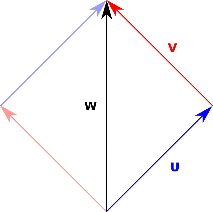
Figure 5 - Vector Addition - Parallelogram.#
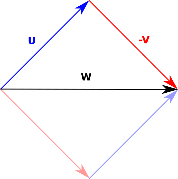
Figure 6 - Vector Subtraction.#
Visually, I had trouble with this situation:
Figure 7 - Basic System with two vectors pointing at each other.#
Forming the parallelogram didn’t help with the intuition. Something simple like this can cause a lot of grief when working on advanced topics. How do we reason about \(\vec{W}\) given that \(\vec{U}\) and \(\vec{V}\) point towards the same point?
Given \(\vec{U}\) and \(\vec{V}\) how do we get \(\vec{W}\). It took me a while to understand what was happening. There are two approaches: a visual approach and an algebraic approach.
In the following diagram, if we play with it a little, we can see that:
Figure 8#
What helped me is to visualize a point at the tail of \(\vec{U}\) and to translate that point to the tip of \(\vec{W}\). How do we get there from here? Take the point and slide it along the direction vector it is pointing to the tip of \(\vec{U}\). Now slide it along \(\vec{V}\), but we can’t. It is pointing in the wrong direction. We can, however, slide it along \(-\vec{V}\). That brings us to \(\vec{W}\).
That intuition helped me reason about vector addition and subtraction. We are pushing points around. It gave me a deeper understanding of the process in a way that I hadn’t comprehended in the past. I was a person that would look up the formula and apply it. That is my engineering training taking hold. In these past years, I have forced myself to understand the mathematics I work with on a deeper level, understanding the most basic building blocks. It has led down some deep rabbit holes.
Alternatively, there is another, more straightforward approach. We can take the algebraic approach. Observe that:
Rearranging and solving for \(\vec{W}\):
The algebra is easier, but it is still a good idea to have an intuition about the nature of the problem and what the mathematics is trying to solve.
Note
The algebraic approach works for two-dimensional and three-dimensional vectors. It should hold for n-dimensional vectors (I have yet to prove it to myself, I would defer to people who are much better educated in this regard). The intuition may not hold true in higher dimensions - I make no claim to that. I am simply presenting what has helped me.
Dot Product#
Wikipedia has an excellent definition of the dot product. It is correct and very informative. But I had a gap in a very fundamental aspect of it. The dot product, scalar product or inner product is defined for vectors \(\vec{a}\) and \(\vec{b}\):
I was always taught that the dot product is the projection of the \(\vec{a}\) onto the \(\vec{b}\). I always thought there was an implied order, that is, you could project \(\vec{a}\) onto \(\vec{b}\) and \(\vec{b}\) onto \(\vec{a}\). If you look at the Wikipedia page, it seems to imply this. However, that thought isn’t supported by the mathematics.
The dot product is commutative - a very important notion:
I am not sure why this was stuck in my head for so long. I had to work through it, reconcile and eliminate the faulty thinking. Looking at figure 9, we can see that the dot product is typically representing one vector projected onto another. I think this is the source, seeing diagrams and definitions that explicitly mention it. If we really think about it, the dot product represents the shortest distance we would travel along a vector (among many other notions that may not be related to geometric distance). If b were shorter than a, we would have the diagram reversed. I think this is similar to the issue in algebra labelling the unknown quantity as x.

Figure 9 - vector a projected onto vector b (attribution).#